Technical details

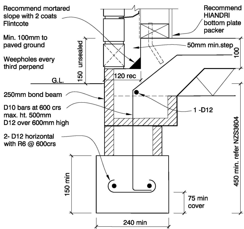
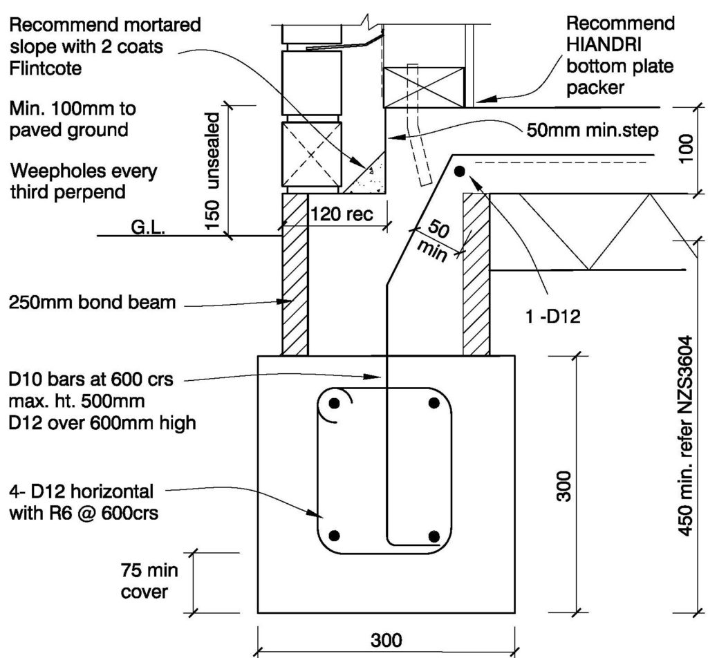
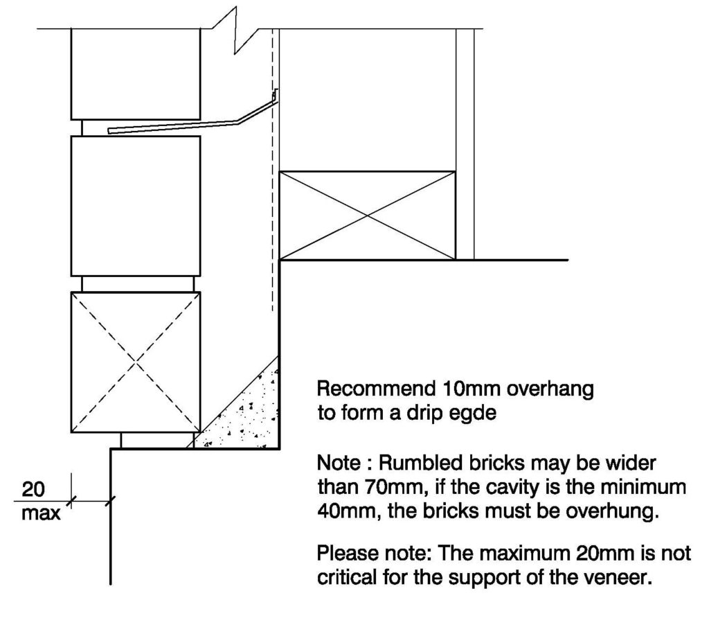
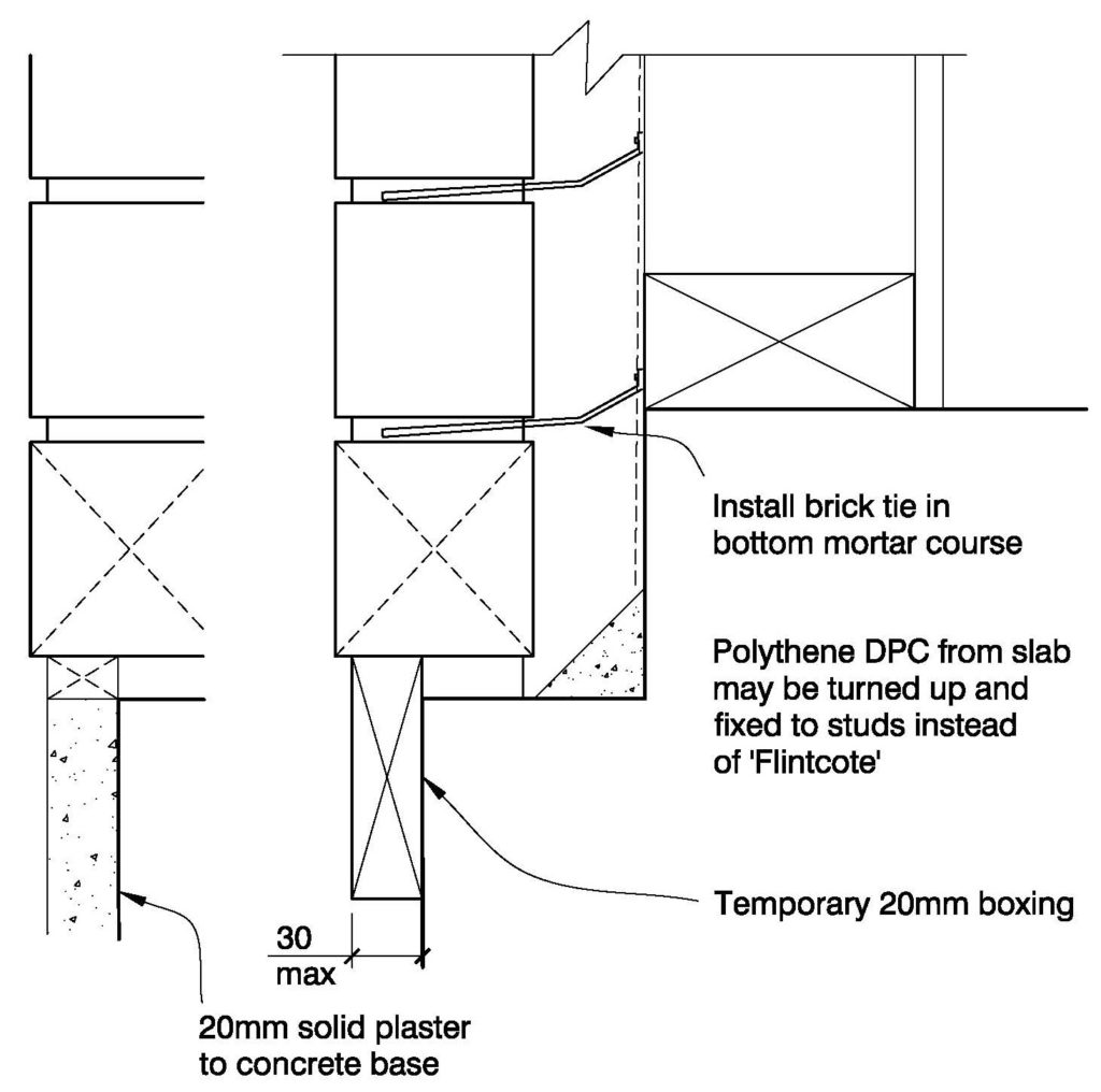
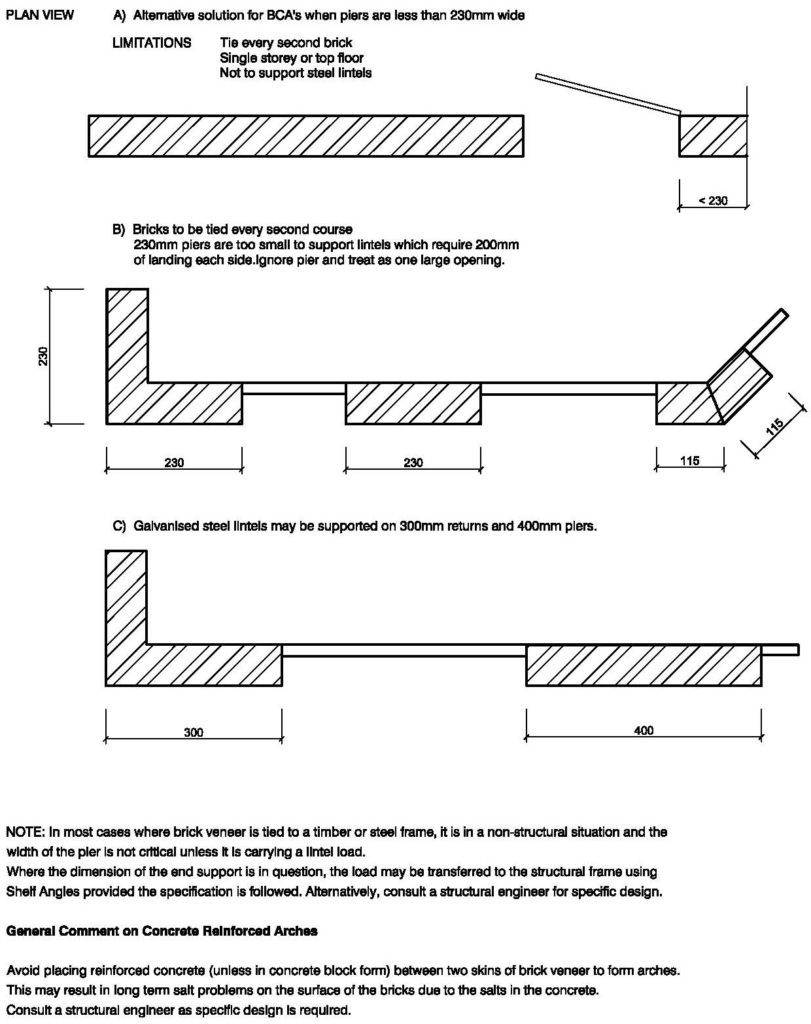
The information and technical details provided correlate with all legislative requirements and generally accepted good trade practice. Although provided as a guide only, common sense and job specific detailing can be added by qualified designers.

Please note these files require Adobe Acrobat Reader or AutoCad software. They can be viewed in DWG Trueview. Please click on the thumbnail to download.

FIG. 1 – Standard Brick Veneer

Clay Bricks – Standard Brick Veneer

FIG. 2 – Standard Internal Corner

Clay Bricks – Standard Internal Corner

FIG. 3 – Standard External Corner

Clay Bricks – Standard External Corner

FIG. 4 – Flat Soffit

Clay Bricks – Flat Soffit

FIG. 5 – Flat Soffit With Brick Mold

Clay Bricks – Flat Soffit With Brick Mold

FIG. 6 – Concrete Slab & Foundation

Option 1: Min. Required for 1 & 2 Storey

Clay Bricks – Concrete Slab & Foundation Option 1 Required for 1 & 2 Storey

FIG. 7 – Concrete Slab & Foundation

Option 1: Standard Detail

Clay Bricks – Concrete Slab & Foundation Option 1 Standard Detail

FIG. 8 – Overhanging Brick Veneer

Clay Bricks – Overhanging Brick Veneer

FIG. 9 – Plastering of Concrete Base [AS]

Clay Bricks – Plastering Of Concrete Base

FIG. 10 – Brick Veneer Below Ground

Clay Bricks – Brick Veneer Below Ground

FIG. 11 – Plinth Base

Clay Bricks – Plinth Base

FIG. 12 – Typical Wall Section

Clay Bricks – Typical Wall Section

FIG. 13 – Brick Veneer on Concrete [AS]

Clay Bricks – Brick Veneer On Concrete

FIG. 14 – Alternative Cavity Solution [AS]

Cavity less than 40mm

Clay Bricks – Alternative Cavity Solution Cavity Less Than 40mm

FIG. 15 – Alternative Cavity Solution [AS]

Cvity exceeding 75mm

Clay Bricks – Alternative Cavity Solution Cavity Exceeding 75mm

FIG. 16 – Deep Reveal - Jamb

Double Stud Framing

Clay Bricks – Deep Reveal Jamb Double Stud Framing

FIG. 17 – Deep Reveal - Jamb

Using Packer

Clay Bricks – Deep Reveal Jamb Using Packer

FIG. 18 – Double Sided Brick

Option 1: External Walls Timer Floor

Clay Bricks – Double Sided Brick Option 1 External Walls Timber Floor

FIG. 18A – Double Sided Brick

Option 2: External Walls Concrete Floor

Clay Bricks – Double Sided Brick Option 2 External Walls Concrete Floor

FIG. 19 – Double Sided Brick

Internal Walls Concrete Floor

Clay Bricks – 19A Double Sided Brick Internal Walls Timber Floor

FIG. 19A – Double Sided Brick

Internal Walls Timber Floor

Clay Bricks – 19A Double Sided Brick Internal Walls Timber Floor

FIG. 20 – Timber Floor

Option 1 – Single Level

Clay Bricks – Timber Floor Option 1 - Single Level

FIG. 21 – Timber Floor

Option 2 - Single Level

Clay Bricks – Timber Floor Option 2 - Single Level

FIG. 22 – Two Storey

Option 1 - Ground Floor Veneer

Clay Bricks – Two Storey Option 1 – Ground Floor Veneer

FIG. 23 – Two Storey

Option 2 - Ground Floor Veneer

Clay Bricks – Two Storey Option 2 – Ground Floor Veneer

FIG. 24 – Timber Floor

Mid-Floor 250 Bond Beam

Clay Bricks – Timber Floor Mid-Floor 250 Bond Beam

FIG.25* – Internal Gutter/Brick [SD]

On Shelf Angle

Clay Bricks – Internal Gutter / Brick On Shelf Angle

FIG. 26 – Window Head - Aluminium [AS]

Clay Bricks – Window Head Aluminium

FIG.27 – Window Head - Timber

Clay Bricks – Window Head Timber

FIG.28 – Window Head - Aluminium

Alternative cladding above

Clay Bricks – Window Head Aluminium Alternative Cladding Above

FIG.29 – Window Head [SD]

Concrete/Stone Lintel

Clay Bricks – Window Head Concrete Stone Lintel

FIG.30 – Bay Window Head [SD]

Clay Bricks – Bay Window Head

FIG. 31 – Greenhouse Window [SD]

Clay Bricks – Greenhouse Window

FIG.32 – Window Head [AS]

Full Soldier Course

Clay Bricks – Window Head Full Soldier Course

FIG.33 – Replacing 90mm Veneer

With 70mm

Clay Bricks – Replacing 90mm Veneer with 70mm

FIG.34 – Cover Jamb Flashing

Clay Bricks – Cover Jamb Flashing

FIG.35 – Window Jamb - Aluminium

Clay Bricks – Window Jamb Aluminium

FIG.36 – Window Jamb – Timber

Clay Bricks – Window Jamb Timber

FIG.37 – Window Sill - Aluminium

Clay Bricks – Window Sill Aluminium

FIG.38 – Window Sill - Timber

Clay Bricks – Window Sill Timber

FIG.39 – Door Jamb - Aluminium

Clay Bricks – Door Jamb Aluminium

FIG.40 – Brick Door Sill [AS]

Clay Bricks – Brick Door Sill

FIG.41 – Negative Soffit

Clay Bricks – Negative Soffit

FIG.42 – Weatherboard to Brick

90˚ Internal Corner

Clay Bricks – Weatherboard To Brick 90˚ Internal Corner

FIG.43 – Weatherboard to Brick

Parallel Junction

Clay Bricks – Weatherboard To Brick Parallel Junction

FIG.44 – Sloping Parapet

Clay Bricks – Sloping Parapet

FIG.45 – Sloping Membrane Roof [SD]

Clay Bricks – Sloping Membrane Roof

FIG.46 – Pergola Fixing

Clay Bricks – Pergola Fixing

FIG.47 – Brick Columns Between Joinery

- Internal/External Feature

Clay Bricks – Brick Columns Between Joinery - Internal/External Feature

FIG.48 – Reinforced Concrete/Concrete Block Column

Clay Bricks – Reinforced Concrete/Concrete Block Column

FIG.49 – Large Width Lintel - UB [SD]

Clay Bricks – Large Width Lintel UB

FIG.50 – Large Width Lintel – Channel [SD]

Clay Bricks – Large Width Lintel Channel

FIG.51 – Head of Arch

Using Formwork

Clay Bricks – Head Of Arch Using Formwork

FIG.52 – Head of Arch

Brick Veneer using angle

Clay Bricks – Head Of Arch Brick Veneer using angle

FIG.53 – Head of Arch

Double Veneer using Formwork

Clay Bricks – Head Of Arch Double Veneer using Formwork

FIG. 53A – Head of Arch

Veneer and slips

Clay Bricks – Head Of Arch Veneer and slips

FIG.53B – Head of Arch

Brick Slips

Clay Bricks – Head Of Arch Brick Slips

FIG.54 – Veneer Over Openings

Using Shelf Angles

Clay Bricks – Veneer Over Openings Using Shelf Angles

FIG.55 – Deck Connection

Option 1: Using 'H' bracket

Clay Bricks – Deck Connection – Option 1: Using H Bracket

FIG.56 – Deck Connection

Option 2: Shelf Angle

Clay Bricks – Deck Connection – Option 2: Shelf Angle

FIG.57 – Deck Connection

Option 3: Using Plates & Bolts

Clay Bricks – Deck Connection – Option 3: Using Plates & Bolts

FIG.58 – Attaching Lightweight Structures to Veneer [SD]

Clay Bricks – Attaching Lightweight Structures To Veneer

FIG.59 – Parapet - External Veneer

Clay Bricks – Parapet – External Veneer

FIG.60 – Parapet Detail [SD]

Full Brick/Double Cavity/Shelf Angle

Clay Bricks – Parapet Detail – Full Brick/Double Cavity/Shelf Angle

FIG.61 – Parapet - Metal Capping

Clay Brick – Parapet Metal Capping

FIG.61A – Parapet Detail

Ventclad/Brick Slip or Veneer

Clay Brick – Parapet Detail Ventclad/Brick Slip or Veneer

FIG.62 – Brick Slips

Eterpan Corner Plan Detail

Clay Brick – Brick Slips Eterpan Corner Plan detail

FIG.63 – Brick Slips

Eterpan Section Detail

Clay Brick – Brick Slips Eterpan Section detail

FIG.64 – Garage Opening

Brick Slips on Eterpan

Clay Brick – Garage Opening Brick Slips on Eterpan

FIG.65 – Soffit End Detail

Clay Brick – Soffit End Detail

FIG.66 – Window Head

Brick Slips on Eterpan

Clay Brick – Window Head Brick Slips on Eterpan

FIG.67 – Window Sill

Brick Slips on Eterpan

Clay Brick – Window Sill Brick Slips on Eterpan

FIG.68 – Two Storey Veneer

Option 1 – Concrete Mid-Floor

Clay Brick – Two Storey Veneer Option 1 Concrete Mid-Floor

FIG.69 – Concrete Mid-Floor

Clay Brick – Concrete Mid-Floor

FIG.70 – Wall At Side Of Roof Slope [SD]

Secret Gutter Option

Clay Brick – Wall at side of roof slope Secret Gutter Option

FIG.71 – Wall At Side Of Roof Slope [SD]

Flashing Option

Clay Brick – Wall at side of roof slope

FIG.72 – Meter Box Head

Clay Brick – Meter Box Head

FIG.73 – Meter Box Sill

Clay Brick – Meter Box Sill

FIG.74 – Typical Pipe Penetration

Clay Brick – Typical Pipe Penetration

FIG.75* – Shelf Angle [SD]

Hidden Joint Rebated Brick

Clay Brick – Shelf Angle Hidden Joint Rebated Brick

FIG.76* – Shelf Angle Under Window [SD]

(Concrete Tile Only)

Clay Brick – Shelf Angle Under Window Concrete Tile

FIG.77* – Top Of Roof Slope [SD]

Clay Brick – Top of roof slope

FIG.78 – Top Of Roof Slope [SD]

Option: Timber Support

Clay Brick – Top of roof slope

HeadFIG.79 – Wall At Side Of Roof Slope [SD]

Option: Secret Gutter - Timber Support

Clay Brick – Wall at side of roof slope

FIG.80 – Enclosed Deck [SD]

Clay Brick – Enclosed Deck

FIG.81 – Base Of Sloping Shelf Angle - Plan View

Small Stop End (eg Ardex BT700 Kickout Flashing)

Clay Brick – Base Of Sloping Shelf Angle

FIG.82 – Flat Soffit & 150mm Frieze Board

Clay Brick – Flat Soffit & 150mm Frieze Board

FIG.83 – Cavity Wall

Maximum Recommended Height 1600mm

Clay Brick – Cavity Wall

FIG.84 – Cavity Wall - High Wind Area

Recommended for walls over 1600mm and High Wind Area

Clay Brick – Cavity Wall High Wind Area

FIG.85 – Single Wall Foundation

Clay Brick – Single Wall Foundation

FIG.86 – Typical Gate Post

Clay Brick – Brick Column Typical Gate Post

HeadFIG.87 – Brick Column - Timber Post

Clay Brick – Brick Column timber Post

FIG.88 – Brick Column - Steel Post

Clay Brick – Brick Column Steel Post

FIG.89 – Brick Column - Concrete Block Column

Clay Brick – Brick Column Concrete Block

FIG.90 – Brick Column - Timber Pile

Brick Veneer – Brick Column Timber Pile

FIG.91 – Single Wall - Capping Options

Clay Brick – Single Wall Capping Options

FIG.92 – Cavity Wall - Capping Options

Clay Brick – Cavity Wall – Capping Options

FIG.93 – Suggested Wall Plan Layouts

Recommend the use of MASONS Bricklock STR and CNR to strengthen walls

Clay Brick – Suggested Wall Plan Layouts

FIG.94 – Bonding Patterns

Clay Brick – Bonding Patterns

FIG.95 – Mortar Joints

Clay Brick – Mortar Joints

FIG.96 – Minimum Circle

With 10mm Mortar Joints

Clay Brick – Minimum Circle

FIG.97 – Flat Segmental Circle

Clay Brick – Flat Segmental Circle

FIG.98 – Piers & Returns

Brick Veneer Openings & Arches

Clay Brick – Piers & Returns – Brick Veneer Openings & Arches

FIG.99 – Soldier Courses

Clay Brick – Soldier Courses

FIG.100 Corbelling

Clay Brick – Corbelling

FIG.102 – Banding

Clay Brick – Banding

FIG.103 – Quoining (Corner Detailing)

Clay Brick – Quoining Corner Detailing

FIG.104 – Dog Toothing

Clay Brick – Dog Toothing

FIG.105 – Galvanised Steel Lintels

Clay Brick – Galvanised Steel Lintels

FIG.106 – Examples Of Window Shapes

Use of Galvanised Steel Angles to Support Brick Veneer

Clay Brick – Examplles Of Window Shapes

FIG.107 – Window Sill Options

Clay Brick – Window Sill Options

FIG.108 – Arches

Clay Brick – Arches

FIG.109 – Curve Formula

Clay Brick – Curve Formula

FIG.110 – Arch Formula

Clay Brick – Arch Formula

FIG.111 – Arch Formula - Tapered Bricks

Clay Brick – Arch Formula Tapered Bricks

FIG.112 – Detail Using Brick Slips

Clay Brick – Detail Using Brick Slips

FIG.113 – Block Retaining Wall

Clay Brick – Block Retaining Wall

FIG.114 – Timber Retaining Wall

Clay Brick – Timber Retaining Wall

FIG.115 – Planter Box

Clay Brick – Planter Box

FIG.116 – Brick Edging

Clay Brick – Brick Edging

© Midland Brick 2019

Website Design by Conceive Creative